Hart's inversors
Planar straight-line mechanisms

Link dimensions:
Crank and fixed: a
Rocker: b (anchored at midpoint)
Coupler: c (joint at midpoint)
![{\displaystyle {\begin{aligned}b&<c\\[4pt]2a&<{\tfrac {1}{2}}b+{\tfrac {1}{2}}c\\[2pt]{\tfrac {1}{2}}c&<{\tfrac {1}{2}}b+2a\end{aligned}}}](https://wikimedia.org/api/rest_v1/media/math/render/svg/13d497f57a6f1006bd13a5acb4a7773e86490c7c)
Hart's inversors are two planar mechanisms that provide a perfect straight line motion using only rotary joints.[1] They were invented and published by Harry Hart in 1874–5.[1][2]
Hart's first inversor
Hart's first inversor, also known as Hart's W-frame, is based on an antiparallelogram. The addition of fixed points and a driving arm make it a 6-bar linkage. It can be used to convert rotary motion to a perfect straight line by fixing a point on one short link and driving a point on another link in a circular arc.[1][3]
Rectilinear bar and quadruplanar inversors

Hart's first inversor is demonstrated as a six-bar linkage with only a single point that travels in a straight line. This can be modified into an eight-bar linkage with a bar that travels in a rectilinear fashion, by taking the ground and input (shown as cyan in the animation), and appending it onto the original output.
A further generalization by James Joseph Sylvester and Alfred Kempe extends this such that the bars can instead be pairs of plates with similar dimensions.
Hart's second inversor

Link dimensions:[Note 1]
Double rocker: 3a + a (distance between anchors: 2b)
Coupler: b
Tip of the A: 2a
Hart's second inversor, also known as Hart's A-frame, is less flexible in its dimensions,[Note 1] but has the useful property that the motion perpendicularly bisects the fixed base points. It is shaped like a capital A – a stacked trapezium and triangle. It is also a 6-bar linkage.
Geometric construction of the A-frame inversor
Example dimensions
These are the example dimensions that you see in the animations on the right.
-
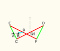
- Hart's first inversor:
- AB = Bg = 2
- CE = FD = 6
- CA = AE = 3
- CD = EF = 12
- Cp = pD = Eg = gF = 6
-
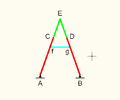
- Hart's second inversor:
- AB = AC = BD = 4
- CE = ED = 2
- Af = Bg = 3
- fC = gD = 1
- fg = 2


See also
- Linkage (mechanical)
- Quadruplanar inversor, a generalization of Hart's first inversor
- Straight line mechanism
Notes
- ^ a b The current documented relationship between the links' dimensions is still heavily incomplete. For a generalization, refer to the following GeoGebra Applet: [Open Applet]
References
External links
Wikimedia Commons has media related to Hart's inversor.
- bham.ac.uk – Hart's A-frame (draggable animation) 6-bar linkage [dead link]


